

 DELIVERING IN-CAR SOUND
Traditional in-car speakers are similar to any regular speaker system, except in the way
the audio signal is transported to them. On-screen warnings given to audiences about
drive-in speakers being of special "high voltage" construction, which rendered
them useless in any other application, were greatly exaggerated. The sound signal is
processed normally in the projection booth; where it is amplified and distributed, via
underground speaker wires, to the individual speakers placed about the lot.
More often than not, the audio is distributed (branched out) to the field through numerous circuits, generally one circuit per ramp, sometimes more. In the event of a short circuit, these individual circuits can be progressively switched off, so that the operator may quickly isolate the ramp with the trouble, thus restoring sound to the remainder of the theatre. This also helps pinpoint the location of the short to facilitate repairs.
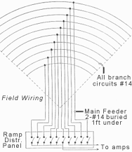
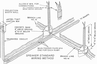
Electrical and diagrammatic representations of field wiring for in-car speakers.
SPEAKER POLE WIRING
There must be at least two wires in each speaker pole, to deliver the sound output from
the projection booth. Termination is made inside junction boxes mounted on top of the
poles; no connections are made underground. The junction boxes contain either a
transformer or a large resistor, depending on the wiring method used. In some
installations, a third wire may also be present to operate downlights (for speaker
standard illumination). In three-wire arrangements, one of the sound wires acts as a
common, providing a return for the downlight circuit. This method saves the expense of
installing a fourth wire.
For safety, downlight circuits should always be low voltage, and never over 24-38 volts. Be extremely careful of existing installations, as there were some drive-ins built with 120 volt downlight circuits! These can kill! It is strongly suggested that any existing 120 volt downlight circuits be switched off and converted to low voltage as soon as possible.
FIELD WIRING METHODS
Throughout the history of drive-in theatres, two different wiring methods have been used
to connect the amplifier system to the speaker system: "series" and
"parallel". This refers to the electrical techniques involved in connecting the
sound feed wires, in the junction boxes of the field of speaker poles (see the
accompanying illustration, for representations of series and parallel wiring).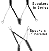
Series
The "series" method was used primarily in drive-ins designed by Motiograph. It
used a resistor in each speaker pole, which dropped the amplifier voltage to a level
suitable to drive a pair of in-car speakers. It was cheap and simple. It had one major
drawback: if a speaker pole was accidentally pulled over, or the wires otherwise cut, the
sound was lost until the break could be found and repaired. It was just like the
old-fashioned Christmas tree lights you may be familiar with, wherein if one bulb burned
out, none of them worked. The series method was tremendously inefficient and wasted
amplifier power.
Mercifully, series-wired fields weren't that popular, but since a handful of surviving installations remain, it's mentioned here for informational purposes. It is not recommended that anyone wire the field of a new or remodeled drive-in "in series".
Parallel
By far, the best method of connecting the sound feed lines to the load of in-car speakers
is via a  special audio, or "matching", transformer (see photo, right).
This permits the field to be wired "in parallel".
Parallel-wired fields have the advantage that, if the speaker pole wires are broken, sound to the remainder of the theatre is unaffected. If the wires become shorted, it is only a matter of switching out the affected section, from a ramp distribution panel in the projection booth, to restore service.
Mounted inside the speaker-pole junction boxes, the transformers step-down a relatively-high amplifier voltage, to a level the in-car speakers can handle. They electrically "match" the speakers to the output of the amplifier. Although the speakers are ultimately causing the power consumption, the amplifier really only "sees" the transformers. A single transformer will power two in-car speakers.
You may be asking why a transformer is needed in the first place; why can't the speakers just be connected directly to the feed lines? Well, if the speakers were all simply "tied" together (in parallel), without the benefit of matching transformers, the resulting electrical characteristics would be such that no amplifier could power it without being destroyed. In other words, it would be the electrical equivalent of a short circuit.
ELECTRICAL CHARACTERISTICS
Components such as transformers and speakers present a certain amount of opposition to the
flow of electricity. In audio applications, this is called impedance and is
expressed in ohms. It is the characteristic of impedance that has to be dealt with,
to successfully design and implement an in-car speaker system.
Speaker Impedance
A typical drive-in speaker has an impedance of 4 ohms. Connected in series, their
impedances simply add. For instance, the total impedance of a pair of drive-in speakers in
series would be 8 ohms.
If we were to connect the two speakers in parallel, however, their impedances would halve. In this case, the total impedance of the pair would be 2 ohms. The individual speakers are still 4 ohms each, but now the electricity has another parallel path to follow; which electrically reduces the opposition posed by just one speaker.
Everytime the number of paralleled speakers is doubled, the total impedance halves. In fact, as more speakers are paralleled, the total impedance keeps getting lower and lower; even though the values of the individual units remain unchanged. If we paralleled 3 speakers, the total impedance would be 1.33 ohms; 4 speakers would be 1 ohm, and so on.
Field Impedance
Impedances of matching transformers are very high and can be nearly 4000 times greater
than that of the speaker. Values range from 750 to 7500 ohms and vary according to
manufacturer. These high values allow a great number of transformers to be connected in
parallel and still present a workable load to the amplifier(s).
The purpose of the transformers will now become clear. Imagine a field of 500 in-car speakers; that's 250 speaker poles, each driven by a 1000-ohm matching transformer. (In other words, 1000 ohms divided by 250 transformers.) The total impedance of the entire field becomes just 4 ohms, or the equivalent of a single speaker! This value is also just right for an amplifier's 4 ohm output terminal--a perfect match.
Now imagine what would happen if a drive-in of 500 speakers were paralleled, without the benefit of matching transformers. The total impedance would plunge to .008 ohms--effectively a dead short!
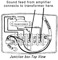
Transformer wiring in speaker pole-mounted junction box.
IMPORTANT POINTS TO REMEMBER
It is necessary that the impedance of every speaker pole transformer be the same value!
Mixing transformer impedances will create an unbalanced condition and improperly load the
amplifier system. This will cause spotty, inconsistent levels on the field and degrade the
overall quality of your in-car speaker sound. Make them all either 1000 ohms, 1100 ohms,
7500 ohms or whatever, but make them all the same. A tip-off that a field has had
transformers mixed up will be huge differences in levels at various speaker poles. Some
speaker locations will produce extrememly loud levels consistently, while others may
always seem too low, regardless of the condition of the speakers installed.
NEVER, under any circumstances, connect in-car speakers directly to the feed lines entering the post! Yes, it seems to give you plenty of volume, but after you do three or four like this, the sound on the remainder of the field will go to absolutely nothing!
HERE'S A SECRET: Divide the impedance of your post transformers (again, they MUST be all the same) by the number of speaker poles (transformers), that will be powered by a given amplifier, to arrive at the total impedance for that group. This determines how the output of the power amplifier(s) will be connected. Obtain the closest match you can, between the field and the output impedance of your amplifier, and you will have terrific sound and lots of volume to spare!
Be aware that if an exact match cannot be obtained between the field and the amplifier, always connect the load (field) to the amplifier output tap that is next LOWEST in value.
For example: Assume the field impedance is 10.6 ohms and you have a choice of amplifier taps of 2, 4, 8, 12, 16, 32, and 100 (ohms). It would be best, in this instance, to connect the field to the amplifier's 8 ohm tap. It is a slight mismatch, but satisfactory. Conversely, if you had connected to the 12 ohm tap instead, excessive current would be drawn; putting the amplifier under stress. In other words, 10.6 ohms is less than the amplifier is expecting to "see" at its 12 ohm tap. Therefore, the load is that much closer to being a short circuit (as far as the 12-ohm tap is concerned).
HERE'S AN EVEN GREATER SECRET: Drive your power amplifiers with audio that has been high-pass filtered (such as obtainable with a Shure M-267 mic mixer), for an undistorted, ear-splitting amount of reserve volume! The filtering removes the low frequency signals below a hundred cycles or so, which eat-up amplifier power and which in-car speakers can't reproduce anyway. You'll be able to hear a front-row speaker from the other end of the field!
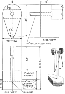
Details for construction of speaker standards.
DETERMINE AMPLIFIER RATINGS
The sound signal must be very strong to power a drive-in full of in-car speakers. 1/2 watt
should be allotted for each in-car speaker, when determining amplifier output ratings (the
old criteria called for only 1/4 watt). For example, a 500-speaker drive-in should have an
amplifier capable of delivering 250 watts output (or a combination of amplifiers driving
portions of the lot, to arrive at the 1/2 watt-per-speaker value).
AMPLIFIERS FOR DRIVE-INS OF THE 90s
Vacuum Tubes Ideal!
Due to the unique characteristics of an in-car speaker system, and for reasons that will
be discussed later, it is strongly suggested that vacuum tube-type amplifiers, instead of
transistor-types, be used in the power-amplifier stages of a drive-in theatre sound
system. Unfortunately, new tube-type amplifiers; like the 100-watt Frazier F-106-C (out of
production for several years), are few and far between.
There is, however, a spark of hope in a growing community of vacuum tube and antique amplifier buffs, who are prompting the manufacture of several new amplifiers. At present, these units are mostly low-power, consumer-grade units (sold for premium prices), and are not big enough for drive-ins. If you are interested, a magazine called "GLASS AUDIO" is published for these hobbyists. It is available at bookstores like Barnes & Noble. While these activities may turn out to be a future source for equipment, it is not commercially viable at the moment. Maybe drive-ins will benefit from their interest later.
Restore Used Equipment
The only thing that makes an old workhorse RCA or ALTEC drive-in amplifier difficult to
utilize, is the unavailability of parts to keep them running. It is solely for this lack
of parts which prevents you from using ancient, dime-a-dozen, Motiograph 7505's to power
your in-car speakers, which would be perfectly acceptable. On the other hand, if parts
were available, they probably wouldn't be a dime-a-dozen!
Some tube amps haven't been made in over 30 years and spare parts inventories have long been depleted. Although tubes, resistors and capacitors are readily available; the reactance components are largely peculiar to a specific make or model; which renders the equipment obsolete the minute the parts supply runs out.
It is suggested that a number of used tube-type units be purchased, to create an inventory of like amplifiers, and simply use the redundant ones for parts. It may even be necessary to cannibalize several units just to build one good, working amplifier. This is not an uncommon practice and is often a theatre's only recourse. This buys some time; you just keep replacing/repairing units, until you are out of parts and they are all dead. Then you have to do something else.
When All Else Fails...
Transistor-type (solid state) amplifiers can be used in drive-ins; some have been
used successfully for years. Understand that the equipment isn't inferior; in fact, it is
highly recommended for exclusive use, elsewhere in the booth. All current stereo and
digital sound equipment in indoor theatres is solid-state; it's performance and
reliability are vastly superior to anything obtainable with tubes, in these applications.
However, tube-type equipment is being recommended here for use as a power amplifier;
the unit which actually drives the field of in-car speakers.
The Weak Link in the Chain
Certain high-quality transistor-type amplifiers, such as the Ashly FTX-2001, can well
handle the power requirements (500 watts) and potential short-circuit conditions of a
drive-in field. They cannot, however, survive high static charges on their outputs,
such as those induced in field wiring, from nearby lightning strikes, at a drive-in.
Tube-type amplifiers are little affected by such charges (short of a direct hit, of
course). This is the primary reason that solid-state amplifiers are not suitable for
in-car speaker service.
If it is determined that solid-state equipment has to be used in the power amp stage, be sure to have emergency back-ups on hand, to insure uninterrupted service of your in-car speaker system.

